Blog
OpenEnergyMonitor

emonTx SMT - Progress Update


Hello Everyone,

Here's another progress update on the emonTx SMT design.

This week I've sent the PCB CAD design files off to get a few prototype PCB's made. It's a very exciting moment, quite a milestone but also nerve wrecking! These prototypes will be assembled by hand and tested extensively. Eventually we plan to get the board ready assembled using factory SMT pick-and-place machines, selling the emonTX SMT as a kit is not an option! We don't plan to discontinue the current through-hole emonTx, we believe there is value in having a simpler through-hole kit version as an option. 

It will be sometime before emonTx SMT's are rolling off the production line, there are many hoops which need to be jumped through before then, but getting the first prototype off the ground is a good step forward! 

As a quick re-cap the main features of the emonTx SMT are:
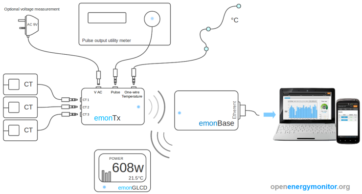
  • Improved accuracy when monitoring low power levels with a programmable gain op-amp input stage on the CT inputs..see blog post
  • Single power supply - Half-wave rectifier AC-DC circuit to power the unit (under basic operation) and monitor mains voltage (enabling real power readings) from a single AC-AC PSU..see blog post
  • Direct USB programming - No USB to UART or FTDI cable required - built in USB host using the ATmega32u4 building on Arduino Leonardo design.
  • On-board Ethernet and multiple wireless radio options – RFM12B will remain the default option.
  • Pluggable-terminal block - Pulse-counting input, 2 x one-wire temperature inputs and other spare I/O broken out on a pluggable-terminal block.
  • Casing - designed to fit in a nice wall-mountable extruded aluminium case with laser cut fascias and external SMA antenna.


For more info, design notes and my general ramblings see my forum post...

Overload Protection of Mains Electrical Circuits by Robert Wall

A new guide by Robert Wall on overload protection of mains electrical circuits.

Robert Wall writes:

The fundamentals.

All electrical circuits must have some means of protecting against overload. This may be done by including a fuse or circuit breaker in the circuit, or the protection may be designed in to the supply that is feeding the circuit. We will only consider fuses and circuit breakers, as these are most likely the device that will be encountered in a normal environment.

How to determine the ratings.

First, you need to know the current that the load demands, under all conditions. You then need to choose a fuse or circuit breaker that will not blow (or trip) when carrying that current, but with only the smallest safety margin under worst-case conditions. Finally, you must choose everything in between – cable, switches, plug & sockets, etc – so that each will safely carry the current that will guarantee that the fuse will blow, or the circuit breaker will trip, under all conditions (paying particular regard to ambient temperature and the ability of the cable expecially to stay cool, i.e. it must not be buried in insulation).

Read the full guide here: Overload Protection of Mains Electrical Circuits

Plug and play sensor nodes


At the moment to get a system up and running you need to do quite a bit of manual firmware configuration, setting unique node-id's selecting different emontx sketches for different functionality, hard coding the emonglcd to get different screens. To add a second emontx you need to add several lines of code to the emonbase and the basestation needs to know the data structure of the sensor nodes.


What if you could upload a standard sketch to each of these nodes, plug your base station into your router, power up an emontx and see emontx 1 appear in a node list in emoncms. Then as you add more nodes they automatically appear in emoncms, no additional base station configuration needed. In time the software could develop to allow remote configuration of nodes such as emontx config and emonGLCD pages: beginning with page template functions as described in the last blog post: emonglcd template based displays

Continue reading the forum post here.

Low-level ADC control: ADMUX


While discussing the 3 phase sketch implementation here: http://openenergymonitor.org/emon/node/467 by Pcunha which makes use of the AVR analog read commands rather than the arduino analog_read function which is a wrapping for these commands JBecker suggested that the analog reference voltage was not being selected correctly, so I had to do some reading up on this on ADMUX and bitwise operators.

So for anyone interested, this is how it works first ADMUX is an 8-bit byte that holds the settings for the analog reference voltage and the analog pin to select:

ADMUX is 8-bit:

 7 bit 6 bit 5 bit 4 bit 3 bit 2 bit 1 bit 0 bit 
ADMUXREFS1REFS0 ADLAR MUX3 MUX2 MUX1 MUX0 
Where:

 REFS1REFS0 Voltage Reference Selection 
 0AREF, Internal Vref turned off 
 0AVcc with external capacitor on AREF pin 
 1Reserved 
 1Internal 1.1V (ATmega168/328) or  2.56V on (ATmega8)
and:

MUX 3...0Single Ended Input
 0000ADC0 
 0001ADC1 
 0010ADC2 
 0011ADC3 
 0100ADC4 
 0101ADC5


So if we want to use AVcc with external capacitor on AREF pin as our voltage reference (which is the default arduino voltage reference) and we want to select ADC2 for example, we would need to set ADMUX to:

 7 bit 6 bit 5 bit 4 bit 3 bit 2 bit 1 bit 0 bit 
ADMUX011

We can use bitwise operations to get there:

This is how its done in wiring_analog.c found in Arduino-1.0/hardware/arduino/cores/arduino

ADMUX = (analog_reference << 6) | (pin & 0x07);


Starting with (analog_reference << 6). The variable analog_reference is set to 1 as default for the atmega328 so 1 << 6 means bitshift 1 left 6 places where 1 in binary is 00000001 and shifting the bits left 6 places moves the 1 to 01000000. The desirable result for setting the 6th bit REFS0 to 1.

If you dont need to select different analog_reference values then we can get 01000000 directly by specifying its hexadecimal: 0x40.

Next looking at the  (pin & 0x07) part.

  • The & 0x07 is actually just for validation, it essentially says only allow selection of ADC0 to ADC5. 
  • The & bitwise operator is the AND operation.
  • 0x07 is hexadecimal whose binary representation is 00000111
  • Selecting ADC2 which is pin = 2 or in binary 00000010
  • The result of 2 & 0x07 = 00000010 AND 00000111 = 00000010.

The last part is the | bitwise operator: OR


(analog_reference << 6) | (pin & 0x07) becomes in our example here 01000000 OR 00000010. Which is equall to: 01000010 the result we where looking for above.

If you would like to read more on the AVR ADC commands see these helpful articles:

https://sites.google.com/site/qeewiki/books/avr-guide/analog-input
http://www.protostack.com/blog/2011/02/analogue-to-digital-conversion-on-an-atmega168/


Configurable single to 3-phase interrupt based EmonTX code by Pcunha

Some great work I'd like to flag up by Pcunha, who has developed a super configurable single to 3-phase interrupt based firmware for the EmonTX.

Its up on github here:
https://github.com/pcunha-lab/emonTxFirmware/tree/master/emonTx_Interrupts

and there is more about it in the forum thread here:
http://openenergymonitor.org/emon/node/467#comment-5481

EmonGLCD Template based display's

I have been thinking about how it could be possible to program an EmonGLCD display remotely or at least specify which displays are shown i.e if you could construct a command to tell the display to:

display solar pv page as page 1, use the solar power value from node 10. 

Skipping for now the how the commands are sent and interpreted, I think the first part of creating these specifiable displays is to convert the current display code into template functions which should be of benefit whether the displays are remotely programmed or not.

Here's my first attempt at this:

draw_power_page( "POWER" ,use, "USE", usekwh);
draw_temperature_time_footer(temp, mintemp, maxtemp, hour,minute);
draws the following page:


draw_solar_page(use, usekwh, gen, 2050, genkwh, temp, mintemp, maxtemp, hour,minute);
draws:

(thanks to drsdre for the icons!)

This is what the full code looks like:

#include <JeeLib.h>
#include <GLCD_ST7565.h>
#include <avr/pgmspace.h>
GLCD_ST7565 glcd;

unsigned long fast_update;

// Fixed values for this example
double temp = 17.4 ,maxtemp = 19 ,mintemp = 16;
int hour = 23, minute = 43;
double use = 252, usekwh = 2.5;
double gen = 1760, genkwh = 4.8;

void setup()
{
  glcd.begin(0x20);
  glcd.backLight(200);
}

void loop()
{
  //-----------------------------------------------------------------------------
  // Display update every 200ms
  //-----------------------------------------------------------------------------
  if ((millis()-fast_update)>200)
  {
    fast_update = millis();
    
    int S1 = digitalRead(15);
    int S2 = digitalRead(16);
    int S3 = digitalRead(19);

    if (S1==1)
    {
      // powerstr, power, energystr, kwh
      draw_power_page( "POWER" ,use, "USE", usekwh);

      // temp, mintemp, maxtemp, hour, minute
      draw_temperature_time_footer(temp, mintemp, maxtemp, hour,minute);
      
      glcd.refresh();
    }
    else if (S2==1)
    {
      // powerstr, power, energystr, kwh
      draw_power_page( "SOLAR" ,gen, "GEN", genkwh);

      // temp, mintemp, maxtemp, hour, minute
      draw_temperature_time_footer(temp, mintemp, maxtemp, hour,minute);
      
      glcd.refresh();
    }
    else
    {
      // use, usekwh, gen, maxgen, genkwh, temp, mintemp, maxtemp, hour, minute
      draw_solar_page(use, usekwh, gen, 2050, genkwh, temp, mintemp, maxtemp, 12,43);
      glcd.refresh();
    }
    
  } 
}

To run this you will need the accompanying icons and templates files, its all available in the EmonGLCD repo here: https://github.com/openenergymonitor/EmonGLCD/tree/master/emonGLCD_Template_Dev

Interested to hear any thoughts on how best to take this forward.

Reading Watt-hour data from an Elster A100C electricity meter using IrDA by Dave Berkeley


If you have an Elster meter this is a fantastic way to read the exact accumulated watt hours that you have generated or used and can compliment and cross check a CT based measurement.

Dave Berkeley writes:

The A100C has an LCD display showing the number of kilowatt hours generated, but it also has two optical outputs. One flashes momentarily each time one watt hour is recorded. The second output is an infrared port which transmits the details of the meter, including accumulated Watt Hours, every second or so.

There are lots of commercial power meter readers around, and many homemade ones too. But they all seem to simply count the 1Wh optical pulses. This does give you an accurate measure of instantaneous power usage / generation, but does not give accumulated totals. If you get a malfunction in the reader you will lose counts. If you count the IrDA output it always gives you accurate accumulated totals.

Read the full build guide here: Electricity Meter Reader

and download the Arduino source code here: elec_meter.ino

The only thing you need to get this running on an arduino or an emontx is a TSL261R optical sensor, the TSL261R has the same pin out as the TSL257 so can be connected to the emontx pulse input.

We've put together a small kit available in the shop of all the components needed to connect it to an emontx including the TSL261R a male 3.5mm jack, 1m of cable and heat-shrink to save needing to get all the components from different places.

EmonGLCD Icons by Drsdre


Drsdre writes:

I've started experimenting with using icon based information with the goal to use the limited real estimate on the LCD more efficient and make the display more attractive.

Current features of this experiment:
  • Icons for current usage, grid, solar and temperature. 
  • Solar and temperature will shown different icons based upon solar wattage/temperature on scale -15 to 40c. Solar maximum value is auto-learning. 
  • If no EmonTX or EmonBase info is received, amount of seconds when last package was seen is shown. 
  • Assigned down button to switch on/off background light. 
Ideas: also add a animated wind energy icon, use an overall more graphical representation based upon a house with panel on the roof, wind mill in garden and connection to grid. It's in a very early stage and I love to hear your feedback.

Forked EmonGLCD sketch with changes can be found on https://github.com/drsdre/EmonGLCD

From the forum thread here: http://openenergymonitor.org/emon/node/888

Almost at the next emoncms release point

Over the last couple of months I have been working closely with Ildefonso Martínez Marchena from Spain on developing emoncms to the next level and we have been making really good progress.

We are almost at the next release point with a lot of big additions including:

Dashboards
  • Support for multiple dashboards
  • A fully visual dashboard editor
  • Public dashboards via username i.e emoncms.org/trystan
  • Support for ckeditor and simeo file manager
  • 8 different dial types and a hot water cylinder
  • LED’s widgets thanks to Lloyd
  • Published and unpublished dashboards for dashboards that are being worked on.
  • A reworked dashboard renderer implementation
Visualisations
Data and core
  • CSV data input and identification by sensor node inputs.
  • Feed Autoconfig
  • New averaging process for creating daily temperature averages.
  • Setup script improvements
  • Thanks to Juan Sidrach for help with general code formatting and multilingual implementation. 
  • Twitter bootstrap based theme.
Multilingual
All this is available now on github and has been of course throughout development. At this stage we are just polishing the release and updating and writing documentation.

emoncms.org
We've got the domain and have the latest version running there off the same server and database as vis.openenergymonitor.org so you can still access your vis.openenergymonitor.org data through emoncms.org.

The idea here is to create a really nice launch page for emoncms and have the live instance hosted there which can be used as a main logging site or for testing before running it on your own server or both. Emoncms.org will still be a beta service for now as its stability and reliability is established.

Bug testing
It would be great if you can try out the new version and let us know of any bugs you find so that we can try to get it as rock solid as possible before this release is complete.

Due to a couple of core implementation changes to visualisations and dashboards many of the visualisation URL’s and dashboard scripting have changed so it best to build any old dashboards from scratch using the new visual editor.

Have a look at the using emoncms documentation here if you need help with any of the steps:
openenergymonitor.org/emon/emoncms/using-emoncms

Please submit any bug details either to the issue tracker on github here:
or on the forums here:
There is also a beginning on code documentation here that may come in useful.

Github

Installation guides
To install emoncms on your own server have a look at these guides:

Let us know how you get on with it.

Open source sailing technology to clean up oil spills


What a great explanation of the importance of open hardware for developing environmental technology and the right conception of business where purpose comes first and profit is there to make the purpose happen rather than technology as a means to make profit, excellent!