Blog
OpenEnergyMonitor

Introducing emonPi: Raspberry Pi based energy monitor


emonPi Raspberry Pi based energy monitor Kickstarter

It's an exciting time for us; this week (on the 1st April, unfortunate timing!) we launched a Kickstarter crowd funding campaign for our emonPi Raspberry Pi based energy monitoring unit

The emonPi has been in development for the past 12 months or so, if you have been lurking on the forums you have probably seen activity on the emonPi's open development forum thread. Thank you everyone who contributed. 

The emonPi has been developed with input from the community, merging the monitoring unit and web-connected base station into a single easy to install and setup energy monitoring solution. 

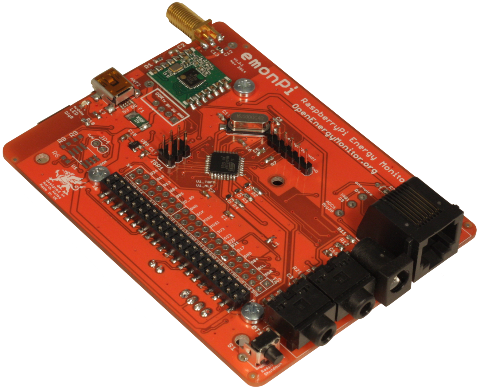
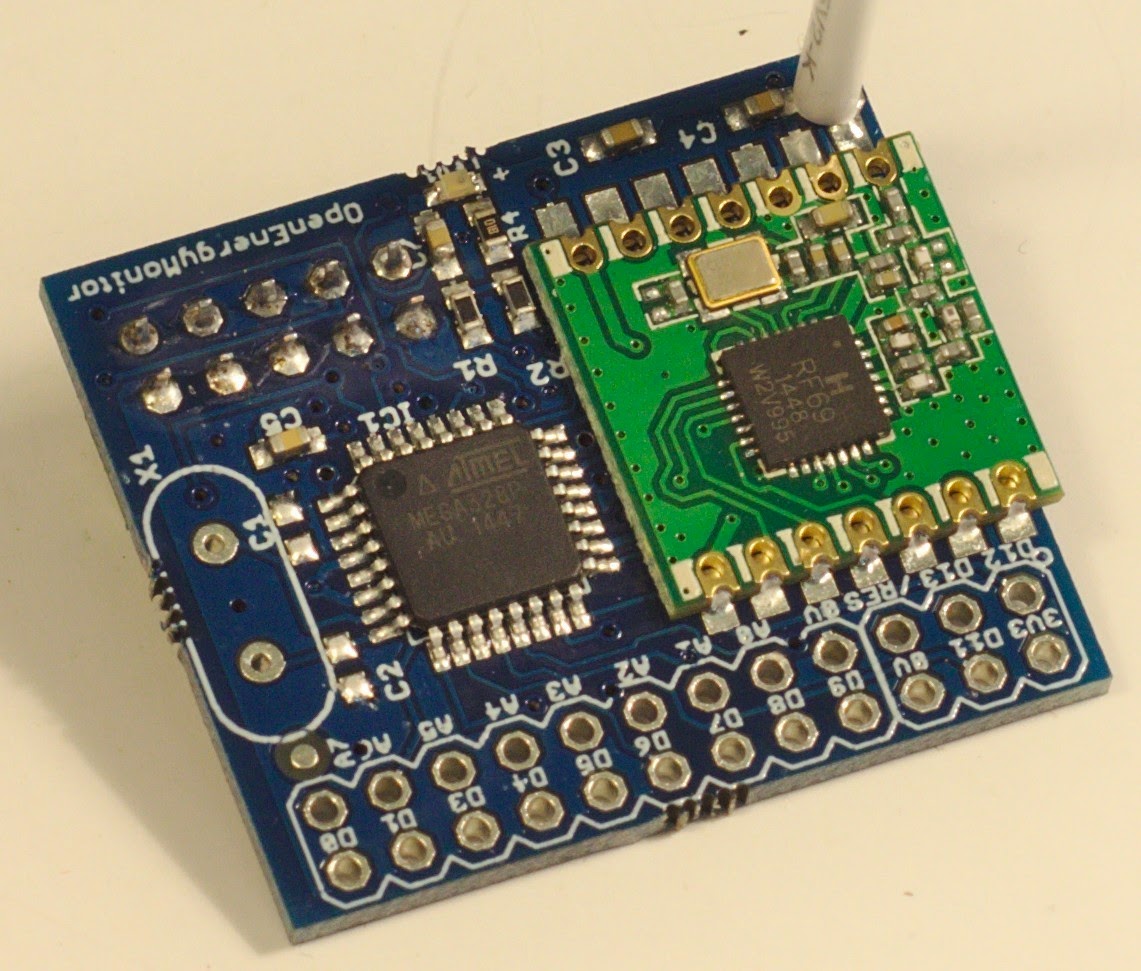
The emonPi is fully open source hardware and software. It's been designed for maximum hackability and customisation being built on a fusion of two popular open source hardware platforms Arduino and Raspberry Pi.

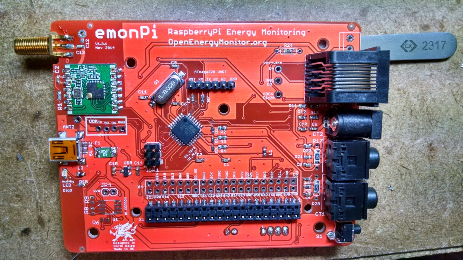
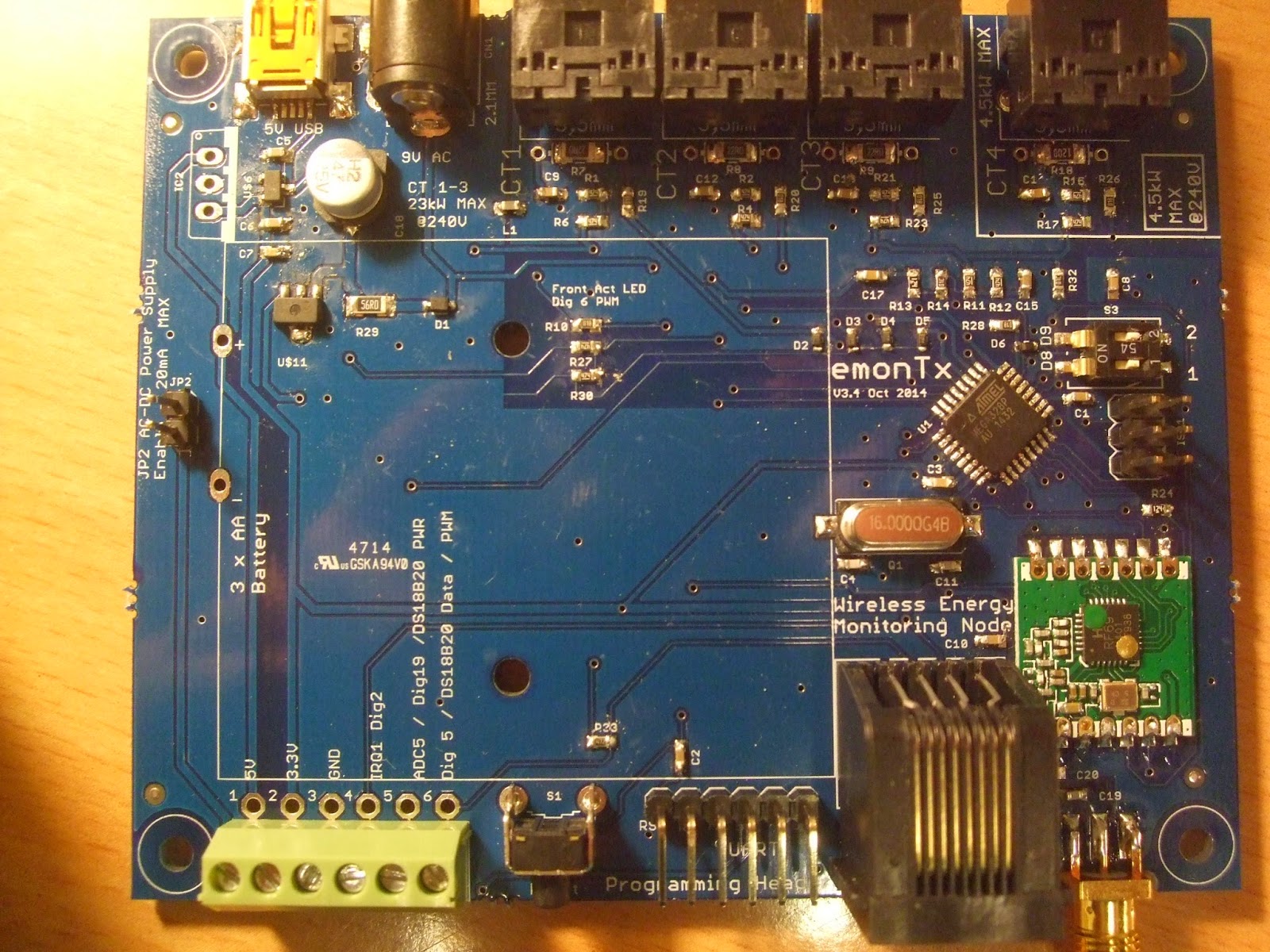
emonPi Technical Features 

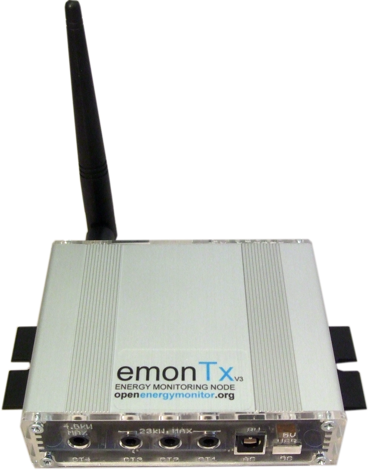
  • Two channel CT monitoring with AC sample input 
  • Compatible with Raspberry Pi model A, model B, model B+ and Pi 2 
  • Arduino compatible ATmega328 with ability to remotely upload sketches vis Raspberry Pi Serial 
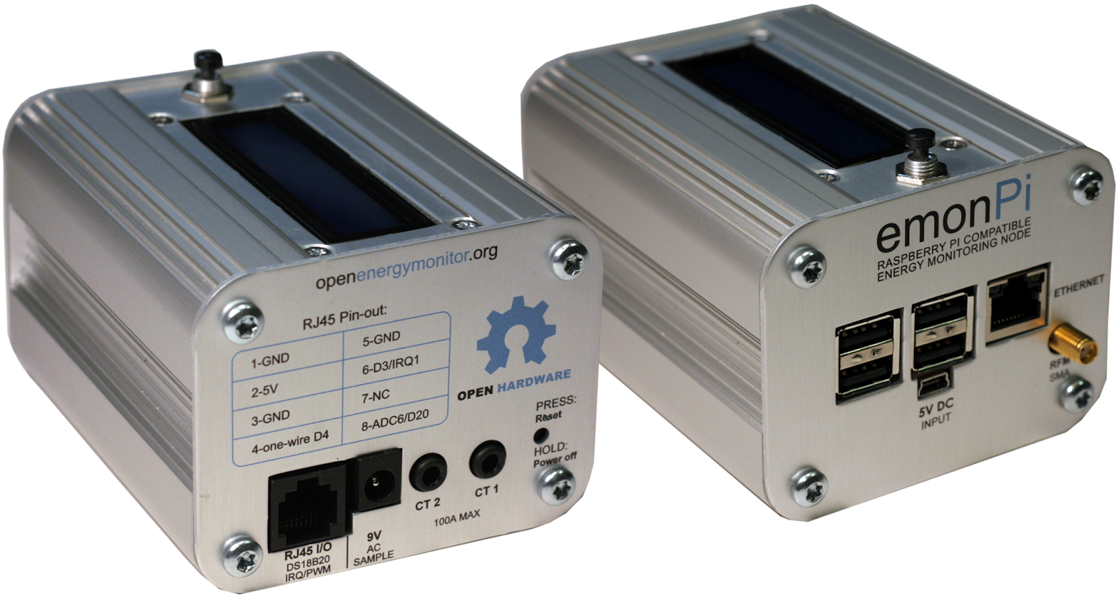
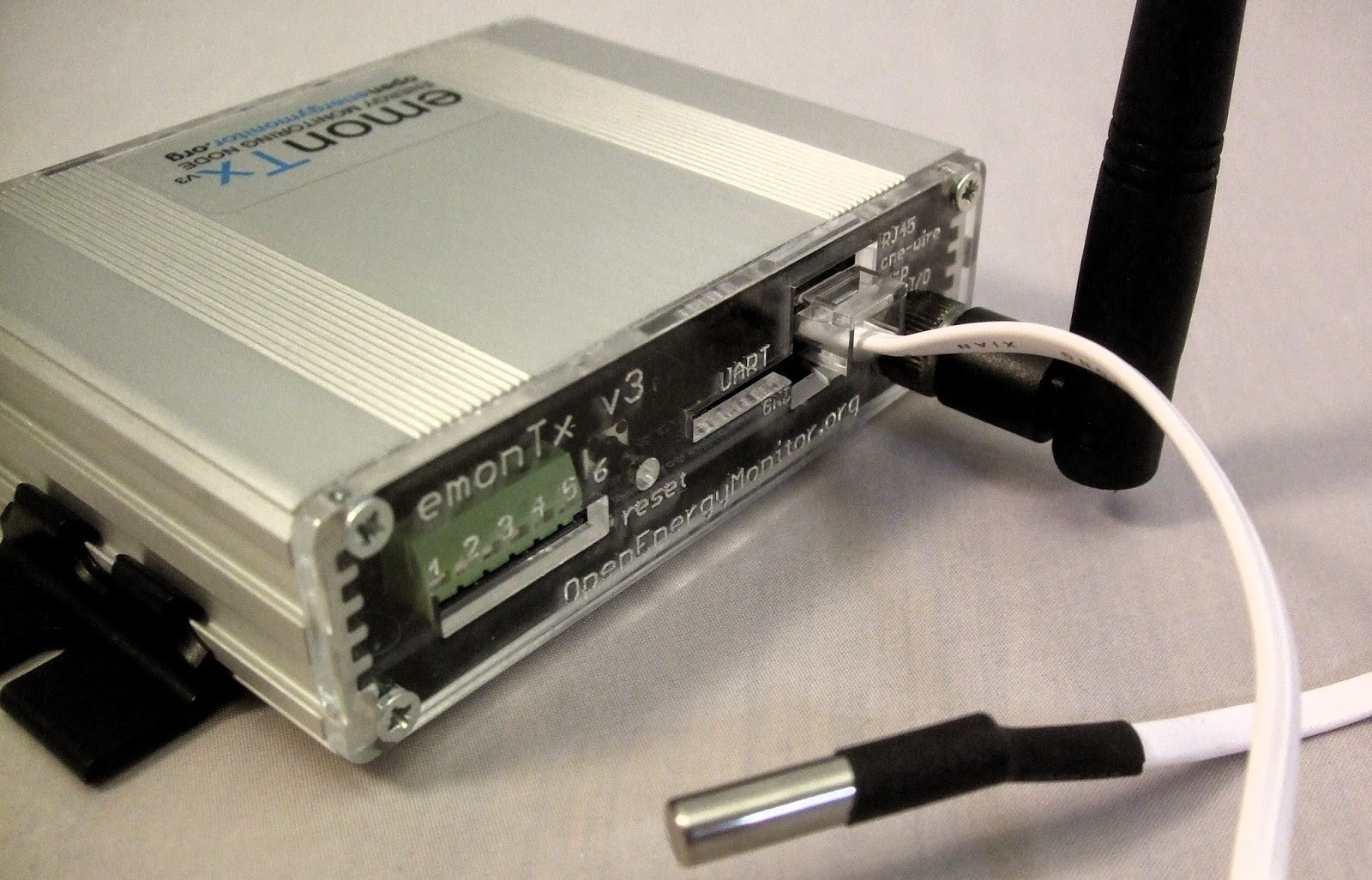
  • RJ45 DS18B20 on-wire temperature bus to allow many temperature sensors to easily be added using a RJ45 breakout board for heat pump monitoring applications 
  • PWM and IRQ I/O's on RJ45 
  • Status LCD with function push button
  • Raspberry Pi shutdown button
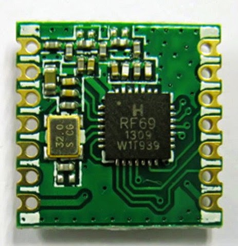
  • RFM12B / RFM69CW with SMA antenna to receive or transmit data from other sensor nodes
  • Option to add OOK (on-off keying) transmitter footprint for controlling remote plugs etc. 
  • Option to add EEPROM to enable Raspberry Pi HAT compatibility (please get in contact if you have experience setting up Linux device tree). 
  • Open-source hardware, firmware and software 
  • High quality custom made, wall mountable enclosure
See the emonPi wiki for more technical info (currently under development).


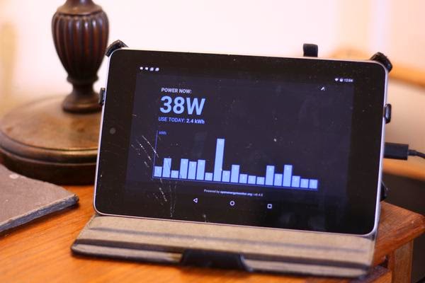
We had fun filming a Kickstarter promo video, demonstrating some applications of the emonPi, Emoncms and the OpenEnergyMonitor system installed around where we are based in the mountain of North Wales, UK.  


Here's a video showing the emonPi installed and talking through how setup will work in practice. Having the LCD to show local IP address, status and uptime etc will no doubt make the system much more user friendly and accessible. 


The Kickstarter will be running until Apr 20 2015 9:46 PM BST, if we haven't reach our funding goal by then we will get nothing! Please help us share and spread the word :-)

Please help us by sharing our Kickstarter page with interested parties

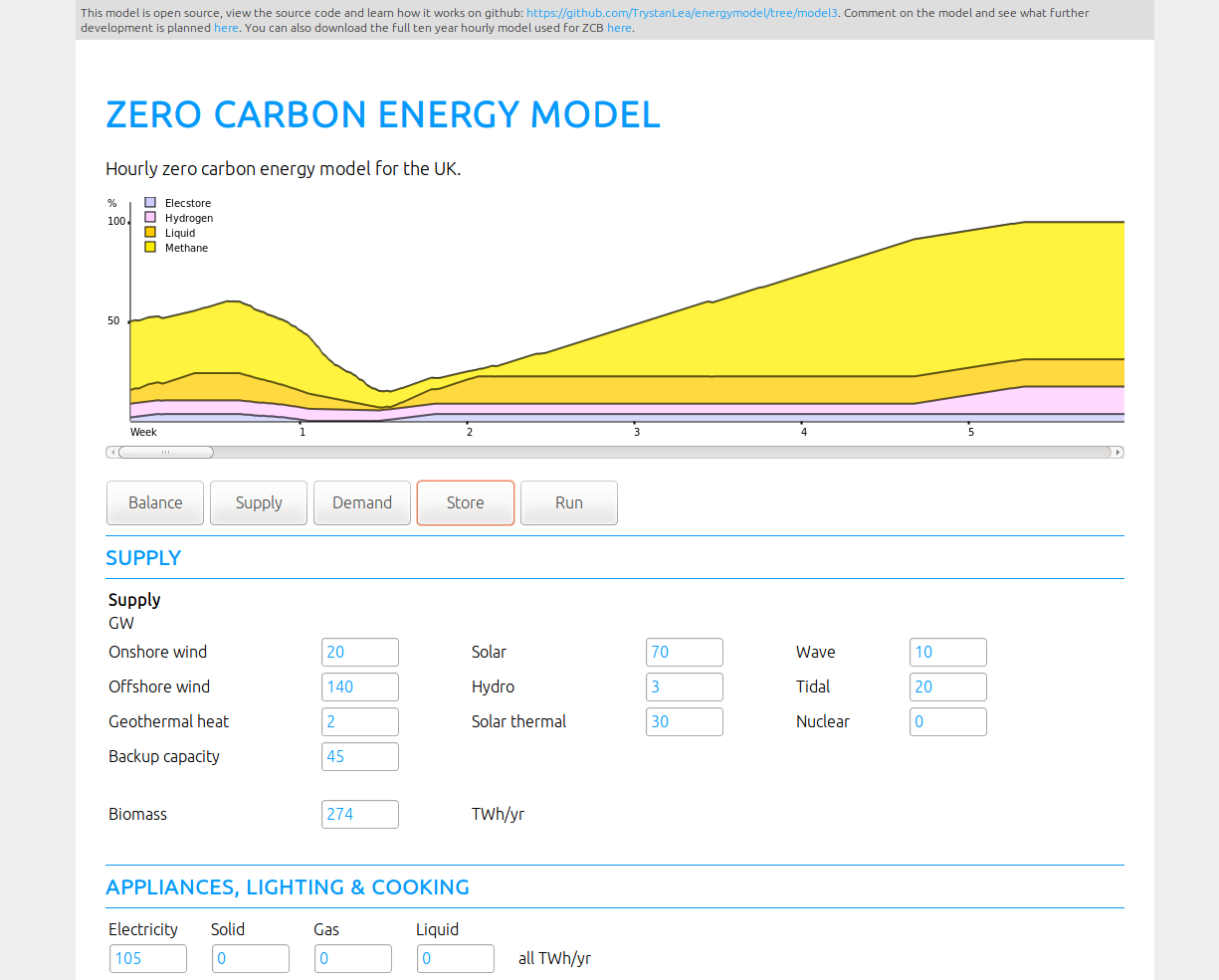
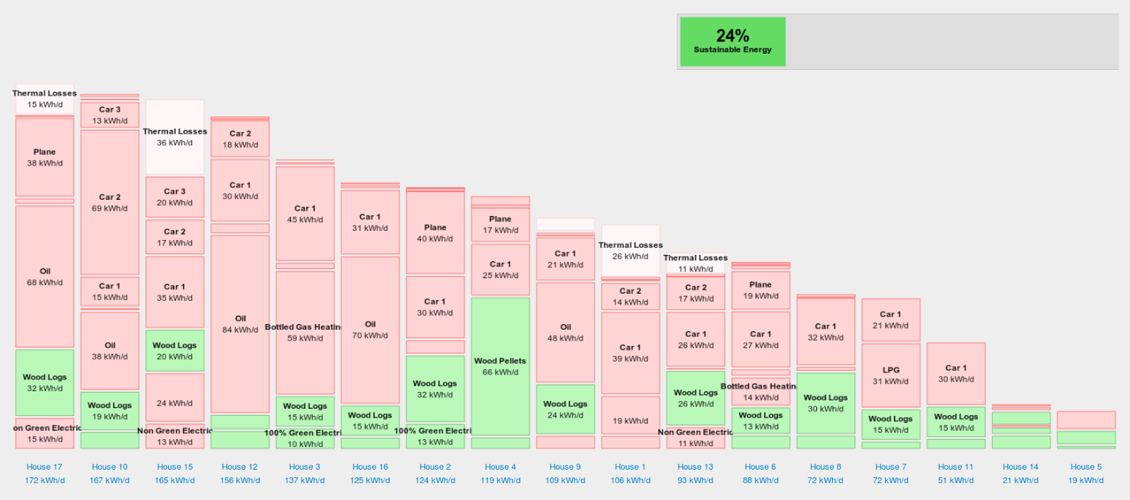
We believe the opportunities and benefits of taking an open-source approach to smart monitoring and control challenges are significant; we hope to encourage others to start projects & businesses that also work towards a zero carbon future in an open way. 


Energy Display Options...

Sadly as of last week we have run out of emonGLCD kits in the shop and have decided to discontinue the emonGLCD for the moment. Preparing the through-hole kits is very labour intensive and the time and skill required to solder assemble is lagging behind our other pre-assembled SMT units.

Work has begun on a SMT pre-assembled replacement (see forum thread). However this would probably require significant investment in injection moulding tooling and commitment to high volume production. This would not would be a problem if we were sure on the design. However, I'm not sure if a standalone display is the right avenue to go down...

I am aware there that there is certainly value in an 'always on' wall mount / coffee table energy display. Being able to easily glance at the display throughout the day when your home really does remind me to switch off lights and appliances when not in use. As well as checking everything is turned off (base level energy consumption) when leaving the house. An always on display gives users a 'feel' for how much energy various devices use as the display increases or decreases in real-time as a device is switched on or turned off.

The future is mobile, everyone has at least one mobile device and increasingly as these devices are upgraded there are a large number of perfectly working just a bit slow older devices which could easily be given a second life as an energy display. This could help reduce the number of devices which end up being recycled or worse put into landfill, therefore helping to save energy in more ways the one! Old second hand android phones or tablets can be picked up on Ebay for less than we could make an emonGLCD!

I recently repurposed an old Nexus 7 tablet (2012 model) with a cracked screen as a home energy display displaying Emoncms MyElectric. I installed an app to keep the screen on all the time when plugged in charging. The tablet uses 5W of power. An added advantage of using a mobile device as an energy display is they are 'mobile'! The display can easily be moved around the house to support investigation power consumption of various appliances.

Much work could be done on the software side to make a really nice packaged android app for Emoncms which would support an energy display mode, useful features might be:

  • Intelligent screen-on-off e.g the display could turn off at night, when energy falls to base level consumption indicating the house is unoccupied 
  • Using the tablets motion / proximity / light sensor to sense movement to turn screen on-off
  • If device has an AMOLED display only certain pixels could be lit up to save power, like on the Moto-x Active Display 
  • Auto start at startup and full screen mode 
  • Home screen widget to be used if user does not want to decicate a devices solely as an energy display or to be placed on current mobile home screen to enable quick checking of power consumption / temperature etc when out and about.    


Emoncms MyElectric on Nexus 7 with cracked screen

A super low power alternative could be to use an old e-reader with an E-ink display. Here's Emoncms MyElectric running on a hacked Nook Touch.

Emoncms MyElectric on Nook Touch
Head over to the forums and let us know what you think...

Real World emonTH Battery Life


The battery on my home emonTH Temperature & Humidity Node has just died for the second time in 14 months. Each set of batteries lasted exactly 221 days (7 months and 9 days)! The 2 x AA alkaline battery voltage started at 3.1V and the emonTH stopped working just after the voltage dropped below 1.2V (final dying breath was at a battery voltage of 0.8V!).  The two AA batteries installed were low cost alkaline batteries unbranded from e-spares. Battery life would not doubt be longer from some quality cells. 

I recommend using rechargeable alkaline batteries if possible in the emonTH, for least environmental impact. See my previous posts on emonTH battery selection and power consumption optimisation

My emonTH had a DHT22 temperature and humidity sensor connected and was set to the default post rate of one minute in-between samples. The unit was running V1.0 firmware (the firmware is now at V1.2, there have been a couple of minor battery life improvements). 

It's very impressive how the DC-DC boost converter onboard the emonTH continues to boost the depleting battery voltage to 3.3V, using this method allows the battery to be drained much further than powering the unit directly. 


RFM69CW Power Consumption

Following on from my post on RFM12B power consumption here's the same measurements for the RFM69CW (see RFM69CW intro blog post).

Current consumption was measured in the same way as explained in the RFM12B post back in July 2013. Voltage drop was measured across 10R current shunt resistor.

A fully populated emonTx V3.4 with a 433Mhz RFM69CW running discrete sampling code with a single CT connected was used in the test. The V3.4 was powered directly with 3.3V DC from bench PSU.

emonTx V3.4 with RFM69CW Test Setup

Test setup illustration


Test Bench
Please excuse my photos of the scope traces rather than screen captures, for some reason the USB socket on the scope did not seem to be working today :-(

Full sample and RFM69CW transmit trace capture

When an AC-AC adapter is not connected the emonTx goes to sleep in between readings. The above current trace shows the ATmega328 waking up for 295ms to sample from one CT channel the spike at the end is the RFM69CW transmitting. The trace below is a zoomed in capture of the RFM69CW transmission and LED. 

RFM69CW transmission current consumption 
The current trace above shows the RFM69CW transmission: 33mA @ 3.3V (109mW) for 4ms. The current spike at the end (up to 39mA) is the emonTx LED. In this test the emonTx was running the standard discrete sampling firmware transmitting a JeeLib packet structure with six integers. Since we were only sampling from one CT four out of the five integers will be zero. 

This equates to a 15 bytes payload plus 9 byte overhead @ 48kb/s. See JeeLib packet structure


In comparison I measured the RFM12B to consume 25.5mA @ 3.3V (84.2mW) for 3ms.

My measurements pretty much agree with the datasheets, here's a comparison table compiled by Low Power Labs:


Even though the RFM69CW does consume more power while it's transmitting it does have a lower sleep consumption than the RFM12B. This increased transmission power should result in an increased transmission range.

I've started a forum thread for discussion: http://openenergymonitor.org/emon/node/10210

Introducing RFM69Pi V3 Raspberry Pi Expansion Board


RFM69Pi on Raspberry Pi B+, also compatible with Raspberry Pi Model B and Pi2

RFM69Pi - just like RFM12Pi but with upgraded radio and more I/O available


The RFM69Pi is a minor update to the popular RFM12Pi Raspberry Pi Expansion board. It adds support for the RFM69CW RF module as well as breaking out as much I/O as possible from the ATmega328 to open up the options for greater connectivity and compatibility. The RFM69Pi was developed with help and inspiration from Nanode RF designer Ken Boak, together we are working on a relay heating controller board using the RFM69Pi. 

The RFM69CW is backward compatible with RFM12B, see blog post introducing the module. From an end user's perspective there should be no difference when using the RFM69Pi over the RF12Pi apart from a new input called RSSI (Received Signal Strength Indication) appearing in Emoncms. 

You must be running the latest pre-build SD card image emonSD-26-02-15.img (now shipping) or emonHub must be updated manually to the latest Development branch version to enabled auto detection of the faster baud rate used by the RFM69Pi (38400 as opposed to 9600 on the RFM12Pi), and RSSI value handling. 

If you're running pre-built SD card image emonSD-13-08-14.img or earlier then emonHub can be updated by running:

$ sudo service emonhub stop

$ cd emonhub

$ git pull 

$ sudo service emonhub start 

check log for errors 

$ tail /var/log/emonhub/emonhub.log


The RFM69Pi is now shipping from our online shop
http://shop.openenergymonitor.com/base-stations/

RFM69Pi Technical Docs Wiki Page:
http://wiki.openenergymonitor.org/index.php?title=RFM69Pi_V3

Open-Source Hardware Design:
https://github.com/openenergymonitor/Hardware/tree/master/RFM2Pi/board/RFM69Pi_V3.1

RFM69Pi Default Firmware:
https://github.com/openenergymonitor/RFM2Pi/tree/master/firmware/RFM69CW_RF_Demo_ATmega328

An open source hourly zero carbon energy system model

I've been doing some work recently with Philip James from the Centre for Alternative Technology on developing a set of open source zero carbon energy system models based on ZeroCarbonBritain that visualise in a javascript based web page application how energy demand can be supplied by a variable renewable energy supply using a mix of storage technologies. You can create your own scenarios, choosing how much wind, solar, storage technologies etc are used.

Its still work in progress but the models we have built so far are now online and can be explored here:
http://zerocarbonbritain.org/energy_model


The source code is all available there too as well as the original ZeroCarbonBritain spreadsheet model: https://github.com/philJam/energymodel

Visualising hourly surplus and shortfall:


Visualising battery, hydrogen, synthetic liquid and gas store levels:


This builds partly on findings and questions raised from our earlier work on the Snowdonia household energy study: here;http://openenergymonitor.blogspot.co.uk/2014/11/snowdonia-household-energy-study.html


The aim will be to extend that analysis to look at the amount of renewable energy and energy storage required to supply the energy demand after implementing measures like building insulation/retrofit, heatpumps and electric transport.


I find it very interesting looking at how all of these different elements can come together to create a zero carbon energy system, to understand better the relevance of different solutions. With a framework like this it becomes more possible to put ideas like smart electric car charging or excess pv diversion to immersion heaters and battery stores in context, to get a better idea of actually how much effect different solutions can have.

Pre-built heatpump dashboards

I've been experimenting with the idea of a pre-built heatpump dashboard - a bit like the myelectric module for home energy monitoring.

The initial concept is up on emoncms.org under the Extras > heatpump tab. The heatpump fan turns in relation to power input a bit like the winderful windturbine.

Configuration is by naming convention at the moment, the dashboard looks automatically for feeds named or containing the words: heatpump_power, heatpump_kwh, heatpump_flow_temp, heatpump_return_temp, ambient_temp and room_temp, using these if present.


Next I plan to extend this for heatpump monitors that also monitor either flow rate or heat output in order to show COP information including a daily power input/ heat output bar graph below the heatpump graphic.

I've been doing this work with John Cantor who is using the OpenEnergyMonitor system for heatpump monitoring.

The source code for this can be found here if youd like to try it on your own install, just drop the folder heatpump into your emoncms modules directory: https://github.com/emoncms/development/tree/master/Modules/heatpump

Introducing emonTx V3.4

Now shipping later this week in the shop is an updated version to the emonTx V3. This is a relatively minor update feature and form factor wise, most users probably won't notice the difference. However when hardware is involved, no update is a minor update!

emonTx V3.4 is now available from the OpenEnergyMonitor Shop


The main changes  are under the hood; the ATmega328 Arduino compatible microprocessor is now is now laid down directly on the PCB. This will help with manufacture and give us a few extra I/O to pay with that were inaccessible on RFu328 module that we used on the original emonTx V3.2. The changes also bring us back in line with JeenNode hardware (IRQ and INT connections) which allow us to use the latest RF12 JeeLib library to support the RFM69CW (see separate post).

emonTx V3.4 Installed

emonTx V3.4 - production units will have battery holder fitted - omitted for photo to show components

Features 

New features on emonTx V3.4 over V3 shown in bold:
  • Measure AC Apparent Power, AC Real power* and AC RMS voltage*
  • 3 x single-phase CT current sensor inputs (100A / 24KW @ 240V max)
  • 1 x high sensitivity single-phase CT current sensor input channel (18.8A / 4.5KW @ 240V max)
  • 1 x RJ45 input for connecting DS18B20 temperature sensors
  • Single AC-AC adapter can power the unit and provide AC voltage measurement
  • An on-board 3x AA battery option with remote monitoring of battery voltage
  • Terminal block access to power rails, digital and analogue I/O and IRQ port for connecting pulse counting sensor / DS18B20 temperature / Aux sensors
  • DIP switch selection of RF node ID and 240V/110V AC adapter selection, see #DIP Switch Config
  • SMA antenna included as standard 
*when AC-AC voltage adapter is connected


emonTx as part of the OpenEnergyMonitor system
The emonTx V3.4 uses an edge SMA connector with an SMA antenna included as standard. We have standardised on 433Mhz (see forum post). The emonTx V3.4 supports and will eventually ship with the new RFM69CW module, this module is backwards compatible with RFM12B. However due to sourcing and lead time issues we have had to use RFM12B on the first batch of 500 units of emonTx V3.4 (now in the shop). When the RFM69CW is used a RSSI (Received Signal Strength Indicator) will appear in emoncms giving indication of signal strength. 

emonTx V3.4 with RFM69CW and edge SMA connector 
The emonTx V3.4 has the addition of an RJ45 socket to allow ease of connecting multiple DS18B20 temperature sensors. Screened RJ45 cabling (Ethernet) is commonly available as well as RJ45 splitters and extenders. This makes a quick and easy way to wire up a house / heat-pump etc for temperature monitoring. Power, GND, IRQ, ADC and PWM I/O's are also available through the RJ45 connector, see wiki for pinout and technical details.

Note: the RJ45 connection is not Ethernet, TCP network switches and routers should not be used 

RJ45 connector used with RJ45 terminal breakout for connection of multiple encapsulated DS18B20 temperature sensors, DS18B20 temperature sensors are also available wired directly on RJ45 connector

DS18B20 Temperature Sensor on RJ45


Certification & Environmental

The emonTx V3.4 is EMC compliant, CE certified. 

The unit is manufactured and assembled in the UK using lead free processes, with RoHS and conflict material free components. The enclosure is made in the UK using recyclable aluminium and recycled acrylic plastic is used for the front and rear fascia. 


Links 


Kettle vs Blanket

One of the things I love about monitoring energy is that it can be used to answer questions and inform decisions.

In my household we have recently purchased an electric blanket, I had always associated such items as an indulgent luxury! However at this time of year the temperature in our bedroom is often only just about in double figures (old property with poor heating and frugal use) necessitating a seemingly moderate luxury of a hot water bottle to warm the bed up a little.   

I assumed using the new electric blanket would result in an increase in our power consumption, however the energy monitor proved me wrong! 

Having the electric blanket on for 30min used about 0.1KWh while boiling 1L of hot water to fill at hot water bottle used about 0.16KWh of energy, 60% more! Also the electric blanket does a much better job of warming the bed then the hot water bottle, after 30min it was almost uncomfortably hot even with an ambient temperature in the room of 11 degrees! 


200W Electric Blanket on for about 30 min

Kettle heating 1L of water to boiling


Introducing RFM69CW

For sometime now the Hope RF RFM12B module has been our RF module of choice. This module was chosen for it's low cost, decent performance and importantly for us, an active development community. On the software side we use the excellent JeeLabs JeeLib RF12 Arduino library.

About a year ago Hope RF announced the RFM12B to be 'EOL' (End-of-Life), there has been a degree of confusion as to what exactly this means; currently manufacture of the module is still taking place and supply is still easily available. However, we acknowledged that the time had arrived to look for alternatives since Hope RF no longer offers support or recommends the RFM12B for new products. 

An obvious alternative that was explored by JeeLabs  is the Hope RF RFM69CW module, it uses SEMTEC designed silicon (as opposed to Silicon Labs in the RFM12B). It's pin-compatible with the RFM12B. Using the updated JeeLib driver the RFM69CW is be backwards compatible with RFM12B helping users of RFM12B to make a smooth transition. Thanks to JCW from JeeLabs and LowPower Labs for the work on developing the RFM69CW Arduino library. We have been working with JeeLabs to source modules and test the driver software.    

Hope RF RFM69CW


I will let JeeLabs/DigitalSmarties introduce the module 

"The recently announced RFM69CW radio module by HopeRF is a compact, powerful radio transceiver module for swapping data packets in the 868 MHz ISM band, using standard and enhanced FSK modulation. Great for sub-compact designs; just 4mm of mounted height from using an SMD precision crystal.

Though consuming a similar level of power, the RFM69CW receiver section can decode fainter signals than the classic RFM12B. The transmitter section *maximum* output power is +13dBm, considerably higher than the +5dBm of the RFM12B. The current drain at these (adjustable) higher power settings is correspondingly higher. With the better receiver sensitivity, many applications will not need to use the higher transmit power settings, potentially saving on battery life.

Comparing like-with-like, pairs of modules will generally have greater range and/or better penetration of walls/ceiling than when using pairs of the classic RFM12B.


The physical module is compatible with the PCB footprint on all current JeeNodes and JeeLinks. For details of the fast-evolving level of software support, see this Forum topic.

Control is via a fast SPI bus with reduced MPU loading. The recommended power supply range of 1.8 < Vdd < 3.6 V can squeeze almost the last energy out of depleting batteries without needing a boost converter."


Comparison tabled compiled by http://www.mikrocontroller.net/articles/RFM69


Early next year we will start transitioning to the RFM69CW, end-users should not notice a difference apart from a new input on the emoncms Inputs page 'RSSI' (Received Signal Strength Indicator), see below.

To simplify manufacture and module sourcing we will be standardising on 433Mhz, we will make available no-RF versions of units for users who wish to solder on their own 868Mhz modules. See forum thread

RFM69CW on the emonTx V3.4 

For early adopters we have limited numbers of RFM12Pi Raspberry Pi Expansion with RFM69CW module in the shop. Using the latest emonHub software (currently in 'Testing' branch) using the RFM12Pi with RFM69CW on a Raspberry Pi should be seamless, emonHub automatically detects the higher baud rate requirement of the RFM12Pi with RFM69CW (56700 as opposed to 9600 with RFM12B RFM12Pi) sets baud accordingly and starts posting RSSI (received signal strength indication) to emoncms.
RFM69CW on the RFM12Pi on Raspberry Pi Model B+

Example RSSI value from emonTH in emoncms

The RSSI readings are very useful as they give a quantitative means of comparing RF performance which should help when deciding on the positioning of units during install and developing better antenna setups.

RSSI readings from nodes setup in my house (mix of RFM12B and RFM69CW) 

RFM69CW on the upcoming emonPi Raspberry Pi Energy Monitoring Shield (due for launch in the new year) 

For more info on the RFM69CW see Building Block Overview Page:

http://openenergymonitor.org/emon/buildingblocks/rfm69cw