Blog
OpenEnergyMonitor

Hardware Manufacture Begins! Part 2: emonTx V3 and emonTx Arduino Shield SMT

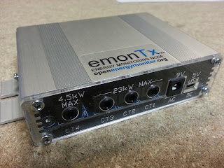
This morning I visited Kaizen Technology in Royston near Cambridge. They're manufacturing the emonTx V3 and emonTx Arduino Shield SMT energy monitoring nodes. We choose Kaizen since we have worked with them before to supply us with components and as far as manufacture goes that have very good capabilities. They are able to perform wave soldering to automate the soldering of thru-hole components. This keeps the cost down on a board like the emonTx V3 where there are many thru-hole connectors. 

Since the emonTx Arduino Shield has got thru-hole components which are inserted from the rear of the board this could not be wave soldered. To keep cost down we will be shipping the emonTx Shield with only the SMT components placed and the thru-hole components supplies as a kit. The emonTx V3 will be fully assembled (SMT + thru-hole), apart from the RFu328 to retain user flexibility as some users might want to use an SRF instead of the RFM12B or even use a different MCU in place of ATmega328. 


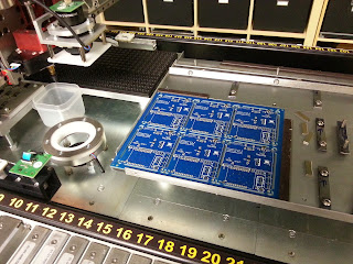
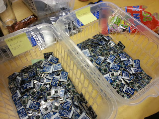
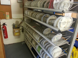
Mm lots of components


Video showing solder paste being applied and pick-and-place doing it's thing

Checking the placements with the pick-and-place camera

Big re-flow oven, wave soldering machine on the right hand side
Manufacture of the emonTx V3 and emonTx SMT shield should be done by the end of this week and we expect to receive them next week. We hope to start shipping the pre-orders soon after: http://shop.openenergymonitor.com/sensor-nodes/

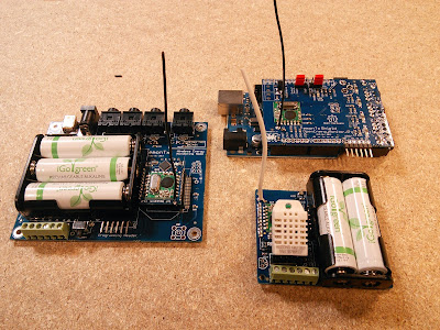
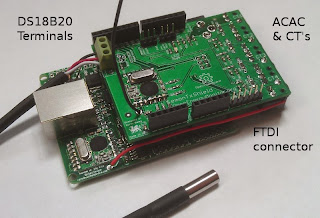
Fully assembled emonTx V3, emonTx Shield SMT and emonTH

Complete emonTx V3 energy monitoring node


Hardware Manufacture Begins! Part 1: emonTH Temperature and Humidity Node

It's a busy for weeks for us at the moment. If you've been following us on twitter you will have see in the last week we have had the production PCB's designs for the emonTx V3, emonTx Shield SMT and emonTH (temperature and humidity) back from our manufactures. This coincided with manufacture of all three units starting this week.

Even though the designs have undergone several iterations and have been extensively tested over the past 12 months or so it was still a nail biting moment assembling, powering up and testing the final designs. Luckily it all went smoothly and all functions on all three designs seem to be working exactly as planned..just as well since we have 500 PCS of each!

Building up the final productions designs..scary! Thankfully it all went smoothly


Final designs for emonTx V3, emonTx Arduino Shield SMT and emonTH all working!
Last week I traveled over to Ciseco  in Nottingham to oversee starting manufacture of the emonTH Temperature and Humidity monitoring node. Ciseco have come a long way since I first visited them over a year ago. They've moved new offices, upgraded their pick-and-place machine and picked up a few more pairs of hands along the way. 

Here's a few photos of the manufacture of the emonTH:

Step 1: solder paste being applied

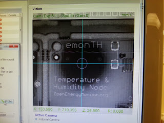
Step 2: Setup the pick-and-place to identify the 'fiducials' on the emonTH...Google it! If you look hard you will see these little shiny round marks on all SMT boards.


Step 3: practice placements


Step 4: let the pick-and-place do it's stuff! I love watching machines at work

Step 5 & 6: Reflow the board in the oven then add the thru-hole bits

Step 7: Test, test and test! Here's show's testing of the RFu328 (ATmega328 MCU + Radio) modules 

Step 8: Done!

Unfortunately we had a few issues during step 7; a some of the RF12B's which were reflowed onto the RFu328's were not working as they should. We think this was down to the large MCU package on the RFM12B absorbing more heat during the reflow process than expected. For the next batch we will look at tweaking the reflow oven's temperature profile. For now we will be hand soldering the RF modules. These sorts of niggles are not uncommon in manufacture, this is why testing is so important. We will be testing the units at several stages before they're shipped to ensure all functions are working. 


emonTx V3 final production design ready to go! 

The emonTx V3 and emonTx Arduino Shield are now in our shop on pre-order. The emonTH should be in the shop in the next few days (just waiting to tie down pricing). We hope to start shipping at the end of this month (November), so hopefully everyone who want's one should get them in time for Christmas. Documentation for all the units is slowly coming together, please bare with us during the next week or so; we hope to have all the documentation and open-source designs ready for we start shipping. Likewise it would be most helpful if you spot any typos (or screaming errors!) in the shop description or wiki documentation please let us know. If you want to take a look the Arduino compatible firmware code for all three units has been pushed to GitHub.

I'm currently on on the train down to London ready to travel to Cambridge tomorrow to meet with another manufacturer and begin manufacture of the emonTx V3 and emonTx Arduino Shield. Stay tuned for another post in the next couple of days! I will also try and tweet some sneak-peak photos of the manufacturing process as it happens tomorrow. 


Documentation highlight: Application guides

To try and bring the work on the application guides more to the fore, I've rearranged the OpenEnergyMonitor Getting Started Guide bringing the application guide list up to the top of the page.


There you will find Robin Emley's documentation on his MK2 PV diverter and Martin Robert PLL PV diverter documentation. I have also made a start on updating the heat-pump application guide and writing a guide on building thermal performance monitoring.

Here's the full application guide list so far:

Home Electricity monitor
Solar PV Monitoring
Diverting surplus PV Power, by Robin Emley
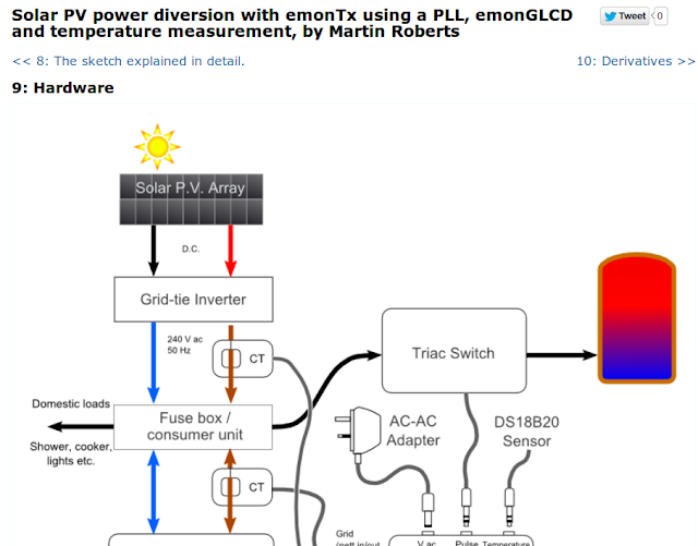
Solar PV power diversion with emonTx using a PLL, emonGLCD and temperature measurement, by Martin Roberts
Building thermal performance monitoring and modelling
Heatpump Monitoring
Solar Hot Water monitoring and control

Documentation highlight: Solar PV power diversion PLL

I would like to highlight the recent addition of some really great documentation written by Robert Wall and Martin Roberts detailing Martin's Solar PV power diversion implementation which uses an emonTx running PLL based firmware,an emonGLCD and temperature measurement.

You can find it here http://openenergymonitor.org/emon/pvdiversion/pll
and its linked through from the main Getting Started Guide.


Improving emoncms performance with Redis plus interesting consequences for SD cards.


As part of recent work to improve the performance of emoncms because of high load's on emoncms.org there is now an emoncms branch that uses redis to store feed and input meta data including last feed time and value fields which where causing significant write load on the server.

Using redis in this way leads to quite a big performance improvement and potentially could lengthen the lifespan of raspberrypi SD card systems significantly.

I've been working on the redis implementation with Ynyr Edwards a good friend and an experienced software developer who recently joined Glyn and I helping us with development and running the shop. Ynyr had been telling me about the usefulness of in memory databases and caching for improving performance for long time. There appeared to be a significant amount of waiting on io going on on emoncms.org and the mysql processlist was full of last time and value updates to the feeds meta data table.

In order to compare the use of mysql versus redis for storing input and feed meta data in emoncms a test was created that was representative of the typical kind of data input seen in emoncms.

The test consisted of a node posting 3 power values, with each value being “logged to a feed” processed into kwh/d data and histogram data. So 9 feeds in total, three of them timestore and 6 mysql based.

The node post rate was set to once a second and the time taken for each request was measured. After single request time's where measured a second test was carried out which involved sending request continuously and measuring the time taken to make 100 sequential requests from which the average requests per second value is determined.

Its important to note that the following results are for sequential requests rather than concurrent requests. Its possible to achieve significantly higher request rates with concurrent requests which spawn many parallel apache processes. Sequantial requests give us a good base line test to work with.

The CPU on the test machine was set to 2.0 GHz x 4 cores

Testing Mysql

The following results show the effect of turing off last input and feed time and value meta data entries in the pure mysql implementation:

Mysql with all metadata switched on:
10x sequential posts, 31ms to 79ms @ 4x 2GHz, average 20 sequential req/s.
With the processor set to 0.8GHz on all 4 cores the request rate was 10 sequential req/s

With a single poster process free-running the CPU is 7.4 us and wait is 11.5 wa

Mysql without input last time value being saved:
10x sequential, posts 26ms to 64ms, average: 25 sequential req/s

Mysql without input or feed last value but still histogram last value:
10x sequential posts: 18ms to 31ms, average: 46-48 req/s

Mysql without input or feed last value or histogram last value:
10x sequential posts: 10ms to 11ms, average 94-95 req/s

Redis 

Here are the results with the redis implementation that's up on github here:

All meta data enabled 11-14ms, 94-95req/s @ 2.0GHz
CPU us 22us, 0.0wa

CPU Performance:
In the redis test the CPU utilisation was around 22%, the mysql CPU utilisation was around 7.4%. Idle CPU us is around 0.2%. Redis is however handling 4.7x the number of requests, if it where handling the same number of requests the cpu us may be around 22/4.7 ~4.7% us.

Wait
We can see a significant reduction in the amount of time spent by the system waiting. With mysql every time a feed was updated, the time and value of the update was written to the mysql feeds table. The first idea was that this waiting was caused by waiting on mysql table locks, testing however with both MYISAM and InnoDB showed similar overall performance even through InnoDB is row locking while MyIsam table level locking. Looking at the disk write rate with vmstat and iotop however showed a really high write rate with mysql so it may be that the waiting was just waiting because the disk was working so hard, see more on this below.

IO Disk write rate:
Here is the output from vmstat with the apache access and redis logs turned off.

Redis

procs -----------memory---------- ---swap-- -----io---- -system-- ----cpu----

r b swpd free buff cache si so bi bo in cs us sy id wa

2 0 0 4282700 352236 2002508 0 0 0 0 1670 44128 20 7 72 0

1 0 0 4281496 352236 2002976 0 0 0 43 1622 44148 20 7 73 0

1 0 0 4280636 352236 2003440 0 0 0 0 1651 44424 21 7 72 0

1 0 0 4280096 352236 2003952 0 0 0 1793 1678 43999 21 6 72 0

1 0 0 4279316 352236 2004416 0 0 0 49 1658 44106 20 7 73 0

MySQL


procs -----------memory---------- ---swap-- -----io---- -system-- ----cpu----

r b swpd free buff cache si so bi bo in cs us sy id wa

1 0 0 4264420 352244 2041008 0 0 0 4280 1695 14833 7 3 79 11

1 0 0 4264904 352248 2039972 0 0 0 4296 1777 15615 8 3 78 11

1 0 0 4264664 352252 2040312 0 0 0 4477 1713 15072 7 3 79 12

1 0 0 4264440 352264 2040420 0 0 0 4355 1700 14982 7 2 79 11

0 1 0 4267364 352284 2037604 0 0 0 4332 1712 15012 7 2 79 12

Using a larger number of vm readings than the 5 listed above the average redis input was 215kb/s and mysql 4430kb/s, idle being 4kb/s. First its surprising how high the mysql write rate is and then second its surprising how large the reduction in the amount of disk writing done is, about 21x less and that's with 4.7 times the post rate. The reduction in the amount of writing could therefore be as much as 100x. The quanitiy of writes cannot only be explained by the kind of writes that are being done in emoncms, most of it appears to be due to ext4 filesystem journaling (61.16% of write capacity) while mysql is only responsible for a couple of percent.

MySQL iotop
Redis iotop 


Journaling
"A journaling file system is a file system that keeps track of the changes that will be made in a journal (usually a circular log in a dedicated area of the file system) before committing them to the main file system. In the event of a system crash or power failure, such file systems are quicker to bring back online and less likely to become corrupted" - http://en.wikipedia.org/wiki/Journaling_file_system.


Raspberry PI SD card installation
The problem with running emoncms on SD cards was that we where wearing the SD cards out in only a few months. If redis reduces the amount of writing by around 100x then this could mean a significantly longer SD card life span.

If in addition to using redis a filesystem without journaling is used the lifespan could be extended even further, although this does increase the risk of data corruption from power failure, but then if such failures are recoverable with a disk check on startup then that’s much better than a worn out SD card.

To potentially improve things further the IPE Debian operating system could be put on a read only partition as is currently done with the oem gateway and the data could be placed on a write partition which could use the ext2 or fat32 filesystem both of which are non-journaling. 

Redis branch on github
If you'd like to try out the redis branch its up on github here:
You will need redis-server installed and phpredis:
Bulk SD Card Loading

Here's a neat little trick which should be useful for anyone needing to flash the same SD card .img onto lots of SD cards in parallel. We have been using it to load up the Raspberry Pi pre-loaded emoncms gateway SD cards. Thanks to @dpslwk for the initial idea.

Tested on Ubuntu Linux 13.10 64-bit

First install dcfldd which is an enhanced version of dd

$ sudo apt-get install dcfldd

I used a USB hub with five SD card readers

$ sudo fdisk -l 

can be used to determine the drive letter of the SD cards, depending on your hard disk configuration it will usually be something like /dev/sdx where x is b-f.  Make sure you check this carefully, selecting the wrong disk can result in one of your hard drives being wiped! dd is not nicknamed 'delete disk' for nothing!


Finally run dcfld selecting each SD card as the output file:

$ sudo dcfldd if=SD_CARD_IMAGE.img bs=4M sizeprobe=if of=/dev/sdb of=/dev/sdc of=/dev/sdd of=/dev/sde of=/dev/sdf

Flashing five SD cards with a 2GB image takes about 4 min for me:


New office space and new hardware units

Thanks a lot for everyone's support, it feel like we're on the verge of starting a new chapter.

The next chapter sees us transferring from self-assembly through-hole kits to pre-assembled ready to go hardware units. This is a step change for us, making it easier to get systems up and running and onto the application (data visualisation and analysis) stage faster. From a Megni (business) point of view we're moving into a new office space and have got some extra pairs of hands helping us out. 

The OpenEnergyMonitor system as a whole can be thought of  as a toolkit for exploring sustainable and efficient energy in our buildings; a toolkit that helps us make informed decisions based on real data and in depth understanding rather than hear-say and overstated product brochures.
emonTx Arduino Shield V2 SMT due to launch in the shop beginning of December

OpenEnergyMonitor fits into and is part of the realisation of the smart, efficient low energy home vision.

The toolkit involves sensor nodes that are placed around a building that record data about the building's operation: its use of electricity, its thermal performance and humidity. The data from these sensors feed directly into visualisation tools as well as being integrated into building energy models that help make sense of this data.

The first part of this work is the monitoring and modelling layer providing you with information that can inform action, whether that's changing a fridge or lighting technology or adjusting heating patterns.

The second part is to integrate control, e.g. controlling a heat pump to heat a building using the most efficient heating pattern. That said, the first part is also control in a sense as it involves informing the user to then instigate some action.

Lots of exciting things to work on in 2014 and beyond! Let's finish with a nostalgic look back at our old lab space where the project was first conceived back in 2009..lots of happy memories:


In the next couple of weeks I will be travelling to Cambridge and Nottingham in the UK to oversee the SMT assembly of our new units, I will try and do some blogging as I go. Fingers crossed this all should go smoothly! If all goes well the new units should be in the shop at the end of November / beginning of December 2013.

Raspberry Pi - A new type of RAM

If you've had trouble booting up your Raspberry Pi then read on...

The latest batch of Raspberry Pi's we have been selling through the shop (manufactured in South Wales, UK) have use a new type of RAM chip.

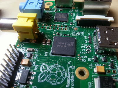
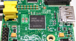
Previously the Pi used a Samsung chip, they have now switched to using a chip manufactured by Micron marked with 3KA18 D9QHN and an 'M' logo. This chip is visible in the middle of the photo below mounted on top of the processor using their cleaver package-on-package technology. This RAM chip is still 512Mb in size

Raspberry Pi with new type of RAM chip
Older Samsung RAM chip
To my knowledge there has been no evidence that the new chip give any performance benefit, the change is probably due to cost or logistic reasons. 

This new chip requires a firmware update to work. Our current SD card images (e.g oemgateway_24sep2013.img) won't boot with the new RAM; static red PWR LED and nothing else. 

To make the Raspberry Pi boot you will need to download the following files and put them in the SD cards FAT (boot) partition overwriting the older files: 

https://github.com/raspberrypi/firmware/raw/master/boot/fixup.dat
https://github.com/raspberrypi/firmware/raw/master/boot/bootcode.bin
https://github.com/raspberrypi/firmware/raw/master/boot/fixup_cd.dat
https://github.com/raspberrypi/firmware/raw/master/boot/fixup.dat
https://github.com/raspberrypi/firmware/raw/master/boot/fixup_x.dat
https://github.com/raspberrypi/firmware/raw/master/boot/kernel_emergency.img
https://github.com/raspberrypi/firmware/raw/master/boot/kernel.img
https://github.com/raspberrypi/firmware/raw/master/boot/start_cd.elf
https://github.com/raspberrypi/firmware/raw/master/boot/start.elf
https://github.com/raspberrypi/firmware/raw/master/boot/start_x.elf

Alternative you could download the whole Raspberry Pi firmware repository (95.6Mb) and copy out the files from the boot directory https://github.com/raspberrypi/firmware/archive/master.zip

I'm currently working on getting a new ready-to-go SD card image download uploaded with the changes above included. This should be available to download soon from: http://emoncms.org/site/docs/raspberrypigateway. Look for the 22nd Oct 2013 image.

All SD cards purchased in the shop after today will have the new image which works on the Raspberry Pi's with the new RAM.

Onwards! 

emonTH Update - Software and Power Consumption

Today I have spent some time writing the software for the emonTH. The goal for the emonTH is for it to last as long as possible from batteries (2 x AA's). The boost converter circuit as highlighted in my previous post will go someway to increasing battery life, however most gains in battery life will come from the software (ATmega328 Arduino sketch) .

The emonTH supports both the DHT22 (humidity and temperature) and DS18B20 either onboard or remote temperature sensor. The default software will search for the presence of either sensor at startup. If both sensors are found it will return humidity from the DHT22 and temperature from the DS128B20. If only the DHT22 is found it will return both humidity and temperature readings from this sensor, finally if only the DS18B20 is found only temperature readings will be returned. In the future I would like to expand the code to support multiple DS18B20 sensors on the one-wire bus.

I have implemented many of the power saving tricks as Martin Harizanov has used in his Funky Sensor code, in particular the his DS18B20 power saving tweaks. Martin has done some great work optimising power and designing some very small low power nodes, his blog is well worth a read.

The emonTH code (in beta) is now up on Github: https://github.com/openenergymonitor/emonth

The power consumption results are as follows, assuming one reading is taken per min and using this battery estimation tool assuming AA capacity of 2200mAh and not taking into account AA self-discharge*

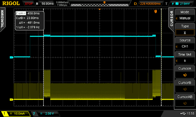
emonTH with DS18b20 temperature only (Vin = 2.6V)


Blue - DS18B20 power digital power pin, Yellow - voltage drop across series resistor. Due to switching noise from the DC converter the scope was not very useful for measuring current (voltage drop across a resistor), the scope was used to measure timings and power was measured with accurate multimeter 
Sleep Current: 0.12mA
On current: 9.7mA for 70ms then peaking to 26mA for 2.8ms for RFM12B transmission, giving average of 10.2mA for 9.8ms

Approximate battery life of 3.5 years*

emonTH with DHT22 (temperature & humidity) only (Vin = 2.6V)


Blue - DHT22 power digital power pin, Yellow - voltage drop across series resistor. Due to switching noise from the DC converter the scope was not very useful for measuring current (voltage drop across a resistor), the scope was used to measure timings and power was measured with accurate multimeter 

Sleep Current: 0.12mA
On current: 9.5mA for 1700ms then peaking to 26mA for 2.8 ms for RFM12B transmission giving average of 9.525mA for 1703ms

Approximate battery life of 1.1 years*


*Stay tuned for the next post on AA battery considerations including how to deal with self-discharge issues...

emonTH Update - Hardware

Since my last post on the emonTH wireless Temperature and Humidity monitoring node good progress has been made.

emonTH cased up


emonTH - unboxed

The most significant hardware change has been the addition of a DC-DC step-up boost converter to step-up the voltage from discharging AA batteries to a steady 3.3V. The boost converter circuit consists of a tiny (SC-70 package) LTC3525-3.3 chip a 10uH inductor and a couple of small 1uF capacitors. The step-up converter is essential for the DHT22 as this sensor does not perform well with varying supply voltage,  specifically once below 3.3V. The addition of the converter will also significantly increase battery life. The LTC3525 was chosen because of its low quiescent power consumption of 7uA and high conversion efficiency of up to 95%.

emonTH LTC3525 DC-DC boost converter circuit

The boost circuit is very impressive, given a minimum input voltage of 0.7V it boosts up to a steady 3.3V.

Using scope with AC coupled probe to examine boost converter output when stepping 2V up to 3.3V with no load: output exhibited 9.3mV RMS ripple at 333Khz

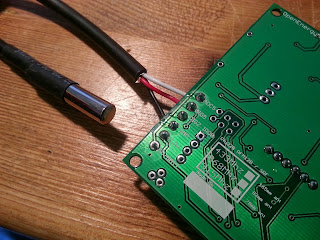
Testing  emonTH external DS18B20 temperature sensor terminal block connection

We hope to have the emonTH in the shop by December.

Stay tuned after the break for update on emonTH software, power consumption and batteries...