Emoncms (early) Heating Control Demo
The next step will be to make a nice user facing interface which allows setting heating control time schedules and pulling in temperature data from emonTH and even making it smart by using energy data to try and detect if someone is home or not. Lots of exciting possibilities now the enabling hardware is in place.
 |
| Gas Combi Boiler Relay Control Unit top left |
Here's a demo of the heating boiler being turned on remotely:
Hardware:
Webserver:Raspberry Pi with RFM12Pi expansion module running emoncms (on external HDD file system): see blog post. The Raspberry Pi and emoncms are also used to log my home power consumption from my emonTx V3, and room temperatures and humidity from my emonTH's. It also mirrors the data to a remote emoncms server for backup.
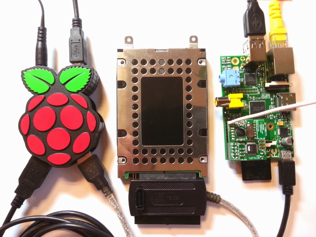 |
| Raspberry Pi with RFM12Pi module with emoncms running locally on HDD file system |
Control Node:
If switching mains voltage is involved only undertake tasks you are comfortable with, making sure everything is isolated before starting work and don't take any chances.
Heating systems vary widely, as does the type of control available. Some heating boilers can be controlled via an RF protocol, this could be preferable since tapping into the boiler direct and switching high voltage would not be required.
My old Worcester Bosch 240 with Honeywell controller requires connecting two terminals together to switch the heating on (see image below). I managed to wire in an additional control wire while keeping the original timer unit in place.
I used an emonTx V2 with JeeLabs relay module, this is just what I had to hand, any RFM12B node with an appropriate relay module could be used. We're looking into making a prototype PCB with an RFM12B, relay unit, on-board power supply and in-line energy monitoring (why not?!). The important consideration here is to make sure everything is properly enclosed and wired up to a high standard if you're controlling mains voltage. DON'T TAKE CHANCES WITH MAINS VOLTAGE.
It's important that the relay module used can handle the current being switched in my case this was only about 500mA @ 240V AC but if you're controlling an electric heating direct this is an important consideration.
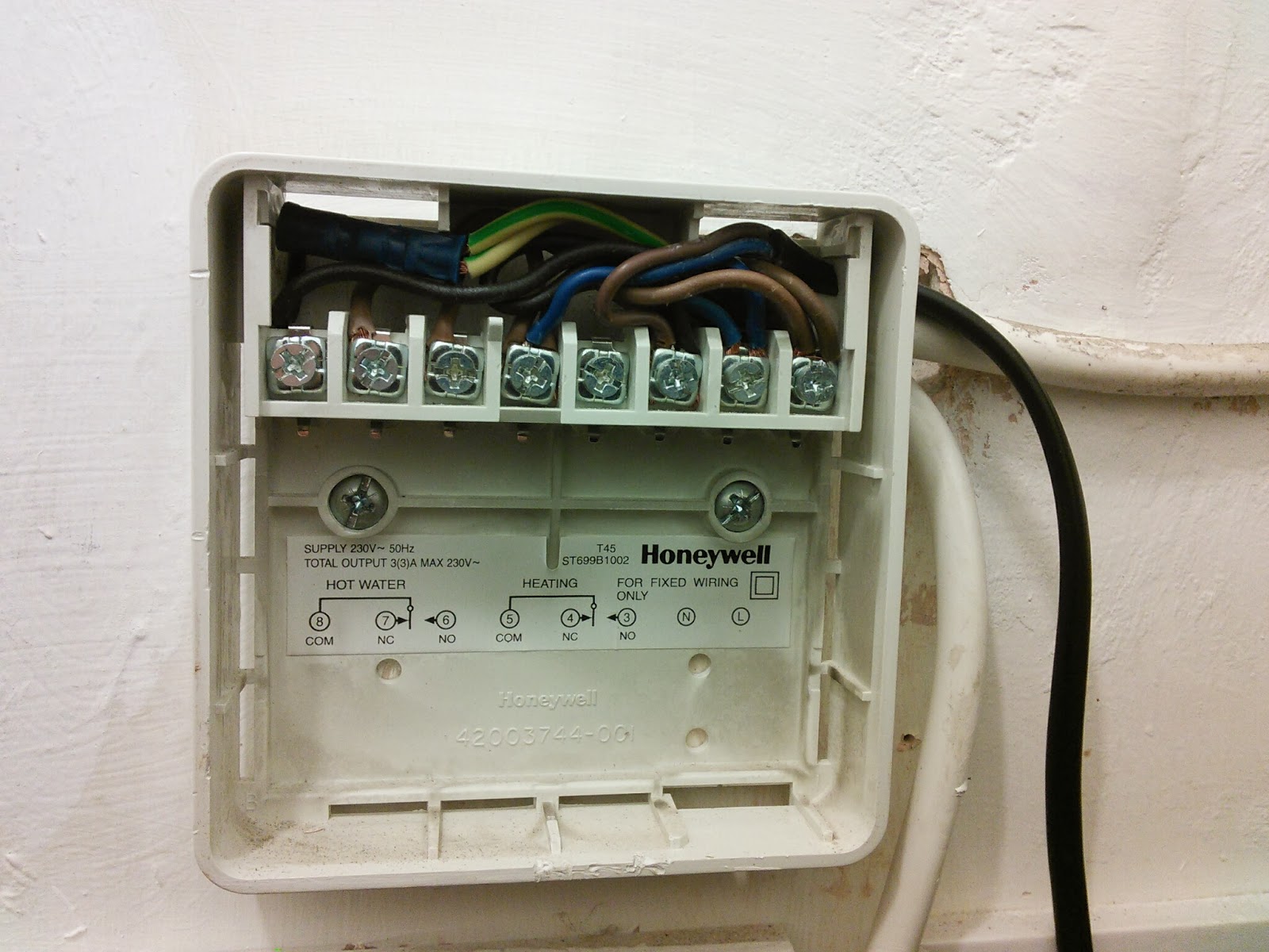 |
| Old Honeywell timer controller unit with front face removed - connect terminal 5 to 3 to turn heating on - black wire goes to relay (caution 240V AC) |
 |
| emonTx V2 with RFM12B and JeeLabs relay module |
Software:
Emoncms Raspberry Pi Serveremoncms running on Raspberry Pi with the new packet generator module, see blog post. This is included in the emoncms Raspberry Pi external HDD image (it's still in beta). For the moment as shown in the video the relay is switched on and off from the emoncms backend web page by browsing to the Pi's local IP address and logging into emoncms and selecting the packet gen module under the extras menu.
 |
| emoncms RFM12B control packet generator module - beta |
To enable control from outside the house the the http port would have to be opened on my router's firewall and a dynamic dns setup on the external IP address. As mentioned at the beginning of this post the next stage is to design a user facing interface dashboard for emoncms control modules.
Arduino Firmware:
I've pushed the Arduino sketch running on the emonTx to the emoncms packetgen module GitHub as an example.
Fail safe
I choose a non latching relay so in case of control unit power failure the relay will default to the open / off position.
I've tried to make the code on the relay control unit as fail safe as possible (independent of Raspberry Pi and network) and as boiler friendly as possible by including a fail safe time after which the relay will default to off (1hr - I'm a frugal user of heating), and a maximum switching rate of 5 min to stop the boiler repeatedly being switched on and off should something go wrong. A hardware watchdog on the ATmega328 was included to try and ensure the microprocessor never locks up.
To engage in discussion regarding this post, please post on our Community Forum.