emonTx V3 Progress Update
The main features of the emonTx V3 have stayed the same:
- ATmega328 Arduino IDE compatible microcontroller
- RFM12B or Ciseco SRF 433/868/915Mhz RF wireless compatiable with RFM12Pi Raspberry Pi emoncms basestation
- 3 x Standard (23kW max) CT channels
- 1 x High sensitivity (4.5kW max) CT channel
- Integrated AC-DC power supply to enable powering the unit from a single 9V AC adapter while also sampling the AC voltage to calculate Real Power and AC Vrms readings
- Low power design with option to power from 3 x AA batteries for Apparent Power (current ony) measurement
- Enclosed in wall mountable extruded aluminium enclosure
- Terminal block connection for optical pulse sensor and DS18B20 temperature sensors
- Pre-assembled SMT electronics
 |
| emonTx V3 with 3 x AA battery's and 1 x CT (Apparent Power setup) |
 |
| Fully assembled with antenna in wall-mount enclosure |
I am currently in the process of obtaining assembly quotes from manufactures as well as performing lots of testing.
 |
| emonTx V3.1 PCB Design |
 |
| emonTx V3.1 Schematic |
The AC-DC circuit that was initially designed with the aid of simulation then bench tested is performing as expected.
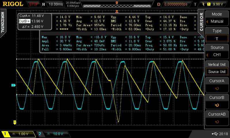 |
| Blue = output from 9V AC adapter Yellow = input to voltage regulator when unit is drawing 7.7mA @ 3.3V, sudden dip is caused by RFM12B firing up to transmit four integer data packets (approx 24mA for 2.7ms) |
To engage in discussion regarding this post, please post on our Community Forum.