emonTx single AC power supply - Part 1 Simulation
The current emonTx V2.x can monitor AC voltage, real power, power factor and direction of current flow, this is possible by using a plug-in 9V AC-AC transformer to provide a stepped-down AC voltage waveform. See Measuring AC Voltage with an AC to AC power adapter in the building blocks section for more details. The emonTx also requires an additional (separate) DC power source, this is usually provided by a 5V USB plug-in adaptor. Obviously it's desirable to do away with one of the power supplies and to use the AC-AC adapter to provide both the AC signal and the DC power to the emonTx. Early tests indicated that using the AC signal to provide a DC power supply adversely effected the quality of the AC signal and therefore the voltage and real power reading of the emonTx. Full wave rectification with a bridge rectifier creates a power supply with floating supply rails and loading the AC-AC adaptor caused distortion of the AC sine wave sample signal. There has been an interesting form thread on the topic of using a single AC power supply for the emonTx. There were number of suggestions for circuits to achieve this. Many of the circuits suggested looked feasible but some added considerable complexity and components such as centre-tapped or isolating transformers. We are keen to use an off-the-shelf certified power supply unit wherever direct connection to mains power is involved. Recently Robert Wall contacted us with a single AC power supply circuit design based on a half-wave rectifier and LDO linear voltage regulator. The circuit only requires an additional two capacitors, two diodes and one resistor to supplement the components we already have on the emonTx PCB. Robert has been very helpful offering his expertise and experience as an Electronic Engineer to the project. The technical testing report on the SCT-013-000 CT and Mascot AC-AC adapter in the building blocks section are all Robert's work. Note: this circuit design is still in development, we are currently at the simulation stage  Fig1. Half wave rectifier AC-DC power supply and AC voltage sample |
The key to Robert's circuit is current limiting resistor R1, this limits the current draw from capacitor C1. The resistor value was chosen to attempt to charge C1 gradually over the positive half cycle. See the labelled waveforms below to see how this works in practice simulation! C2 is a de-coupling capacitor and R3-R5 reduce the AC sample to the correct magnitude and bias ready to be sampled by the ATmega328 ADC.
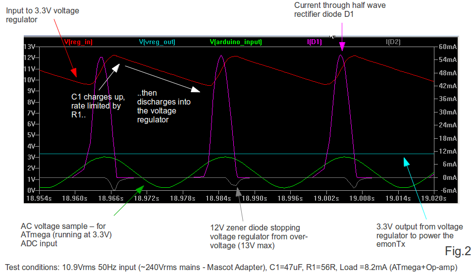 |
| Fig2. Simulation waveforms under normal operating conditions |
To demonstrate the effect of the current limiting resistor R1 the simulation was ran with R1= 1 ohm, see the labelled waveforms in Fig.3 below. The capacitor C1 now charges up quicker drawing more current from the AC-AC adapter, this loads the adapter creating a 'dip' in the AC sample waveform. This will negatively effect the voltage and real power reading on the emonTx.
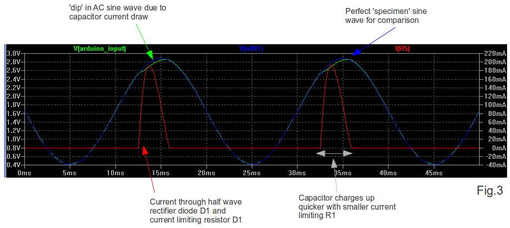 |
| Fig. 3 Demonstrating the effect of low value current limiting resistor R1 |
The next step is to move beyond the virtual; build up a prototype to see if it performs in practice like the simulation suggests!
I've posted the LTspice simulation files used to generate the simulation waveforms on the forum: http://openenergymonitor.org/emon/node/704 To engage in discussion regarding this post, please post on our Community Forum.