Reducing noise, adding a capacitor
I recently bought a new laptop and when I plugged it in to the mains and connected up the energy monitor via usb and monitored the current of one light the current value it read was much higher than what my reference meter said it should be. I got the following results:
Load description: One light
Energy monitor power supply: Laptop mains connected.
Energy monitor: 1050mA reference meter: 189mA
Load description: One light
Energy monitor power supply: Laptop running off battery.
Energy monitor: 186mA reference meter: 189mA
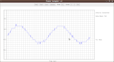
I loaded up the waveform sampler program to see what was going wrong and saw this when the laptop was connected to the mains:

When the laptop was not connected to the mains the fluctuations largely disappeared.
I then checked to see what the energy monitor would read when powered by an external supply rather than the laptop supply. The energy monitor was now a lot closer to the reference meter than before:
Load description: One light
Energy monitor power supply: External power supply
Energy monitor: 225mA reference meter: 191mA
The laptop is not connected to the mains here.
Load description: One light
Energy monitor power supply: External power supply
Energy monitor: 215mA reference meter: 191mA
The laptop is connected to the mains here but on a separate plug socket.
Interestingly the laptop still produces an effect even when its plugged into another socket not part of the measuring setup. The other thing to note is that the energy monitor current is higher by about 20-35mA with the external power supply than when powered by the laptop running off its battery.
It would clearly be nice to get rid of the noise when the laptop is connected to the mains and the difference in measured current between the different power supplies.
Reading through the Atmel AVR465 application note, they use a 10uF capacitor across the biasing voltage divider to stabilise the DC level. I added the capacitor and low and behold the noise and difference in power supplies disappeared and now the results are much better :) The energy monitor now reads
Load description: One light
Energy monitor power supply: Laptop mains connected.
Energy monitor: 194mA Reference meter: 191mA
Energy monitor power supply: Laptop running off battery.
Energy monitor: 194mA Reference meter: 191mA
Energy monitor power supply: External power supply.
Energy monitor: 193mA Reference meter: 191mA
The laptop is not connected to the mains here.
Energy monitor power supply: External power supply.
Energy monitor: 193mA Reference meter: 191mA
The laptop is connected to the mains here but on a separate plug socket.
The variation between power supplies and the effect of the noisy laptop power supply is significantly reduced.
Here's a screenshot measuring the same lamp as I was measuring above with the energy monitor powered from the laptop connected to the mains but now with the 10uF capacitor across the 2.5V bias:
Very steppy but this is due to the small magnitude of the signal versus the ADC resolution which is expected, the large noise fluctuations have disappeared.
Here's the new circuit diagram:

Component values
CT sensor turns ratio – for the efergy sensor seems to be 1:1500 which means the current in the secondary windings will be 1500 times less than the current in the mains primary winding.
RsensI - Dictates the range that the current can be read over.
- 56Ohms gives a current range of 0 to 47Amps (with efergy CT, turns ratio: 1500)
- 100Ohms gives a current range of 0 to 26Amps (with efergy CT, turns ratio: 1500)
C1 – The bias stabilizing capacitor.
- Noise decreases as the capacitor size increases.
- Energy monitor start-up time increases as capacitor size increases – this is the time taken for the capacitor to charge, measured as the time it takes for the current measurement to reach within 20mA of the final value. Only a noticeable delay the first time you put the energy monitor on.
- Atmel recommends a 10uF capacitor in their AVR465 app note.
- 10uF works well, I tried a couple of other values and there doesn't seem to be a very noticeable difference at 4.7uF, 1uF, 0.1uF, needs further testing to establish exactly how much difference there is between the values.
Rvd – 2x equal sized voltage divider resistors
- Increasing the resistor size decreases current consumption in the voltage divider.
- Increasing the resistor size increases noise due to high impedance.
- Increasing the resistor size increases the energy monitor start-up time due to charging of C1.
- 2x 100k resistors and a C1 of 10uF gives a start-up time of 16s.
- 2x 10k resistors and a C1 of 10uF gives a start-up time of 4s.
I've also removed the 100Ohm current limiting resistor from the above circuit as I'm not sure that it was really doing anything, I put it in there out of general practice, feel free to use one if you like.
Its also worth adding a 10uF capacitor on to the voltage measurement circuit in the same place. I will discuss that in more detail soon along with some other changes to the voltage measurement electronics.
To engage in discussion regarding this post, please post on our Community Forum.