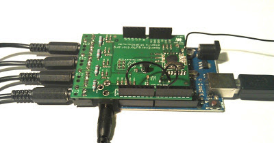
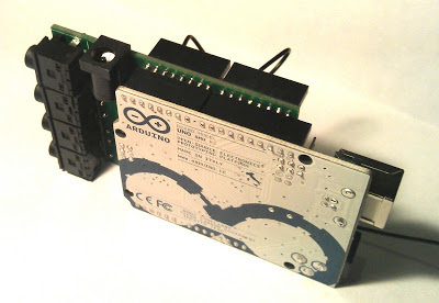
Emontx Shield SMT with new layout in development
Several weeks ago we got an email with a series of pictures showing the problem that the emontx shield does not stack well with many of the base boards and other shields it may be used in conjunction with.
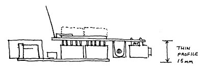
It got me thinking about different ways the shield could be arranged that would make it stack better with a variety of different boards. The main idea I had was to move the AC-AC Adapter and CT inputs over to the other side of the PCB away from the side the Ethernet and USB sockets are usually located on most of the Arduino boards and the NanodeRF. The second idea was to mount these sockets on the underside of the PCB which allows for a really thin profile NanodeRF + EmonTx shield stack which I think is pretty neat if a little unconventional. Here's the concept drawing:
As you may be aware I have not really ventured into PCB design much before (I usually work on software) but its been something I wanted to do for a while so I thought Id have a go at the emontx shield redesign as its one of the simplest layouts. With Glyn's helpful guidance I started by loading the existing schematic and board files for the through hole emontx shield in eagle, I then ripped up all the existing PCB tracks, rearranged the components in different layouts and switched the resistors and capacitors over to SMT packages. Here's a screenshot of the resultant board design:
I spend most of my dev time writing lines of code which becomes a visual output in a second step, PCB design is a different experience as its all immediately visual, dragging and dropping pcb tracks, trying to see if this track that way or another in its place looks neater, its a nice change. If your intrigued to have a go I'd recommend installing eagle, loading up one of the board designs that are all up on solderpad and experiment with routing tracks, maybe adding/removing a temperature sensor.
The PCB's arrived on Tuesday, I built it up and have started to test it, so far everything seems to be working, energy monitoring part, RFM12, Led, DS18B20 temperature sensor, Arduino Uno, Arduino Duemilanove. Next I will test the NanodeRF and Id also like to test an Arduino official Ethernet shield.
Things to improve
There is a very slight misalignment on the ISP header that needs fixing although it still stacks together fine and Glyn pointed out that the option to choose different SS (SEL) and IRQ pins for the RFM12 could be achieved using a manual jumper rather than solderable pads. Id also like to add a terminal for the DS18B20 on the edge of the board for neater connection of temperature sensor strings.
Once these are fixed we will get a run of boards made, it will probably be another month or two at least until its in the shop as these things take time.
Open Hardware Schematics and Board files
All available on solderpad here:
To engage in discussion regarding this post, please post on our Community Forum.


