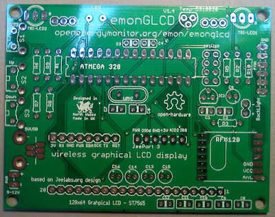
emonGLCD V1.4
Introducing the current version of the emonGLCD. This post is a bit later than planned, we have actually been selling the V1.4 through the shop for the past month or so. This version features some minor incremental improvements rather than a new design.
The main changes to this revision are:
- This LCD power is connected to the 3.3V rail instead of instead of 5V. This will fix the problem with the LCD going blank due to over voltage, discussion thread here. *
- The external power connection now routed through voltage regulator this means it can accept an input from 5-12V
- The push switches are now active high, each with their own 10K pull down resistor, R7 and R8 are two additional 10K pull down resistors.
All other functions work exactly the same as previous emonGLCD versions.
See the bottom of the main emonGLCD documentation page for a full change-log detailing the different versions over time.
*Running the LCD at 3.3V instead of 5V is now within spec for the LCD unit, however running the LCD at a lower voltage did flag up an error in the orientation of C13 and C14 see forum discussion thread here. A note has been added to the build guide to instruct the insertion of C13 and C14 the opposite way round to what is marked on the PCB.
 |
| emonGLCD V1.4 - Assembled (RFM12B missing) |
 |
| emonGLCD V1.4 PCB - Front |
 |
| emonGLCD V1.4 - Rear |