Single AC power supply + voltage sensing
The idea of using the same AC-AC power adaptor for both sensing voltage and supplying power to emonTx has been discussed on the forums for months (see this topic), and about six weeks ago Glyn posted a simulation of a possible circuit.
I had the time this weekend to give it a try, bought the necessary components and put it all on a breadboard. After a sleepless night I can confirm: It works!
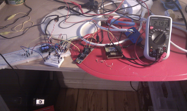
Here is my messy setup:
Small modifications had to be made to get it to work: I added a 1uF cap between 3.3v and GND to filter out some noise and redefined the voltage calibration coefficient in the code.But the main problem (took me all night to figure it out) is that the usual emonTx sketch wont work straight ahead. The line that lights up the LED (on pin 9) at the end of the setup loop has to be commented out, otherwise the setup won't work. It's no problem to flash it 2ms after each packet is sent, but apparently having it on in the beginning will prevent the program from starting. Maybe there isn't enough current to do it and move on (I must say that I use 10k ohm resistors for the voltage dividers). If it's not that then maybe full wave rectification could help.I used a humble Xprotolab to measure the Vin, Vout and at some other points in the circuit. It behaves almost exactly like the simulation. fft also shows very little noise.Would be great if other members could repeat this experiment to see if the results will be the same.Next step: Voltage sensing on the base ;)
To engage in discussion regarding this post, please post on our Community Forum.
I had the time this weekend to give it a try, bought the necessary components and put it all on a breadboard. After a sleepless night I can confirm: It works!
Here is my messy setup:
