Non invasive current sensing method
A current transformer works in a similar way to a normal transformer. The primary coil in this case is the mains wire. Opening the sensor up you can see the secondary coil wrapped around the other side of the transformer core.
I found this paper which is about hall sensors but there is an overview of current transformers there too. Their description of how a current transformer works:
“The primary current (AC) will generate a magnetic field that is coupled into a secondary coil by Faraday’s Law. The magnitude of the secondary current is proportional to the number of turns in the coil, which is typically as high as >1000. The secondary current is then sensed through a sense resistor to convert the output into a voltage. ”
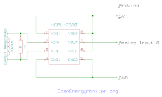
The next step is to convert this voltage in to a form usable by the Arduino. The analog inputs on the arduino require a voltage in the range of 0 to 5V and so the voltage needs to be biased by 2.5V and should not have an amplitude of greater than +-2.5V.
There's probably an easier and cheaper way to do this but the HCPL -7520 chip used in the invasive current sensor does the job simply and is what I had on hand. The isolation provided by the chip isn't required in this case and so Vcc1 and Vcc2 can be supplied by the same source. Here's a picture of the circuit and the schematic.
 To find a suitable value for the sense resistor I connected up the above circuit to Arduino analog input 0 and the invasive current sensor to input 1 allowing comparison of both waveforms using a slightly modified power sampler program. I know that the current waveform from the invasive current sensing method is correct and so it is possible to calibrate the non invasive method by matching the both waveforms. The voltage across the sense resistor is proportional its resistance multiplied by the current flowing through it and so by trying different values for the sense resistor it is possible to match both waveforms. The closest fixed value resistor I could find that gave matching waveforms was 22Ohms. The current waveforms from both methods match quite nicely:
The graph show the current waveform with a laptop connected. The invasive current measurement is 0.5A rms and the non-invasive method gives 0.445A rms which is quite close, with a potentiometer with a range of about 50 Ohms the sense resistor value could be tuned and the result improved.
So that's current done but to get a value for power we also need a voltage measurement. Unless its possible to infer the voltage waveform from the current waveform, devices like the efergy energy monitor can only be measuring current. So how do we get a power measurement? Apparent power is calculated as the rms voltage x rms current, to read more about power measurment have a look here. The rms voltage is nearly always in the uk 230V however the rms current varies as the load is changed. The current transformer method can measure rms current and so we can calculate a value for apparent power with this method.
My efergy energy monitor however has stopped working (maybe after I tried to work out how it worked by taking it apart) and so I cant compare the results. If I get it to work again, I will post up the results. However the results do agree with the invasive current sensing method and so should be good :) To engage in discussion regarding this post, please post on our Community Forum.